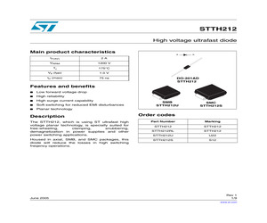
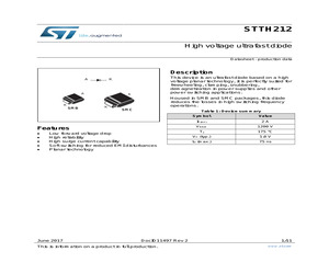
s A IF(AV) 2A VRRM 1200 V Tj 175C VF (typ) 1.0 V trr (max) 75 ns K DO-201AD STTH212 Features and benefits Low forward voltage drop High reliability High surge current capability Soft switching for reduced EMI disturbances Planar technology Description SMB STTH212U SMC STTH212S Order codes The STTH212, which is using ST ultrafast high voltage planar technology, is specially suited for free-wheeling, clamping, snubbering, demagnetization in power supplies and other power switching applications. Part Number Marking STTH212 STTH212 STTH212RL STTH212 STTH212U U22 Housed in axial, SMB, and SMC packages, this diode will reduce the losses in high switching freqency operations. STTH212S S12 June 2005 Rev 1 1/9 www.st.com 9 STTH212 1 Electrical characteristics 1 Electrical characteristics Table 1. Absolute Ratings (limiting values) Symbol Parameter Value Unit VRRM Repetitive peak reverse voltage 1200 V V(RMS) RMS voltage 850 V 2 A IF(AV) IF(RMS) Average forward current = 0.5 DO-201AD Tl = 105C
 10 Pages, 127 KB, Original
s A IF(AV) 2A VRRM 1200 V Tj 175C VF (typ) 1.0 V trr (max) 75 ns K DO-201AD STTH212 Features and benefits Low forward voltage drop High reliability High surge current capability Soft switching for reduced EMI disturbances Planar technology Description SMB STTH212U SMC STTH212S Order codes The STTH212, which is using ST ultrafast high voltage planar technology, is specially suited for free-wheeling, clamping, snubbering, demagnetization in power supplies and other power switching applications. Part Number Marking STTH212 STTH212 STTH212RL STTH212 STTH212U U22 Housed in axial, SMB, and SMC packages, this diode will reduce the losses in high switching freqency operations. STTH212S S12 June 2005 Rev 1 1/9 www.st.com 9 STTH212 1 Electrical characteristics 1 Electrical characteristics Table 1. Absolute Ratings (limiting values) Symbol Parameter Value Unit VRRM Repetitive peak reverse voltage 1200 V V(RMS) RMS voltage 850 V 2 A IF(AV) IF(RMS) Average forward current = 0.5 DO-201AD Tl = 105C
 9 Pages, 137 KB, Original
TM High Voltage TO-220AC SOD-93 DOP-31 TO-220AB F126 ISOTOP TO-247 IF (av) A 1 1 1 1 Vrrm V 200 200 200 600 trr max (*typ) ns 15* 20* 20* 80* Vf V 1 0.97 0.97 1.3 @ If A 1 1 1 1 2 2 2 200 200 1200 15* 17* 75* 1 1 1.75 2 2 2 SMA SMB SMB STTH2R02A STTH2R02U STTH212U 3 3 3 3 3 3 200 200 200 1000 600 600 16* 35* 35* 75* 30* 60* 1 0.75 0.75 1.7 1.7 1.3 3 3 3 3 3 3 DO-201AD DO-201AD DO-201AD DO-201AD DO-201AD DO-201AD STTH3R02 STTH302RL STTH302 STTH310 STTH3R06 STTH3L06 4 200 16* 1.05 4 D-PAK Prices are in sterling & exclusive of VAT Package DO-41 DO-41 SMB SMB Mftrs. List No. STTH1R02 STTH102 STTH102A STTH1L06U STTH4R02B-TR 2 Price Each Mftrs. List No. Order Code 1+ 25+ 100+ 250+ 1K+ STTH12R06D STTH15R06D STTH102 STTH102A STTH302 STTH310 STTH802CB STTH806TTI STTH6003CW STTH1L06U STTH3R06 STTH5L06 STTH8L06FP STTH8R06D STTH30R06CW STTH1002CB STTH1002CT STTH2002CFP STTH2002CT STTH3L06 990-7882 990-7904 990-7866 990-7874 990-7955 990-7980 993-5975 980-3831 980-3815 990-7939 990-7998 990-8005 993-5991 990-
 144 Pages, 26045 KB, Original
print 5.11 (0.201) 1.54 (0.061) 1.54 (0.061) 3.14 (0.124) 8.19 (0.323) millimeters (inches) DocID11497 Rev 2 9/11 Ordering information 3 STTH212 Ordering information Table 8: Ordering information 4 Order code Marking Package Weight Base qty. Delivery mode STTH212U STTH212S U22 SMB 0.110 g 2500 Tape and reel S12 SMC 0.243 g 2500 Tape and reel Revision history Table 9: Document revision history 10/11 Date Revision Changes 28-Jun-2005 1 First issue 12-Jun-2017 2 Updated cover image. Removed DO-201AD package. DocID11497 Rev 2 STTH212 IMPORTANT NOTICE - PLEASE READ CAREFULLY STMicroelectronics NV and its subsidiaries ("ST") reserve the right to make changes, corrections, enhancements, modifications, and improvements to ST products and/or to this document at any time without notice. Purchasers should obtain the latest relevant information on ST products before placing orders. ST products are sold pursuant to ST's terms and conditions of sale in place at the time of order acknowledgement. Purchasers are
 11 Pages, 391 KB, Original
he maximum short-circuit duration must be limited to the maximum value given in the semiconductor data sheet. Figure 14 illustrates how diodes DVCE1 and DVCE2 may be used to measure switch desaturation. For insulation, two diodes in SMD packages are used (STTH212U for example). RRES connected to VISO guarantees current flow through the diodes when the semiconductor is in the on-state. When the switch desaturates, CRES starts to be charged through RRES. In this configuration the response time is controlled by RRES and CRES. In this application example CRES = 33 pF and RRES = 62 kW; if desaturation is too sensitive or the short-circuit duration too long, both CRES and RRES can be adjusted. Figure 15 shows the recommended PCB layout and corresponds to the schematic in Figure 13. The PCB is a two layer design. It is important to ensure that PCB traces do not cover the area below the desaturation resistors or diodes DVCE1 and DVCE2. This is a critical design requirement to avoid coupling capacitance w
 24 Pages, 1993 KB, Original


